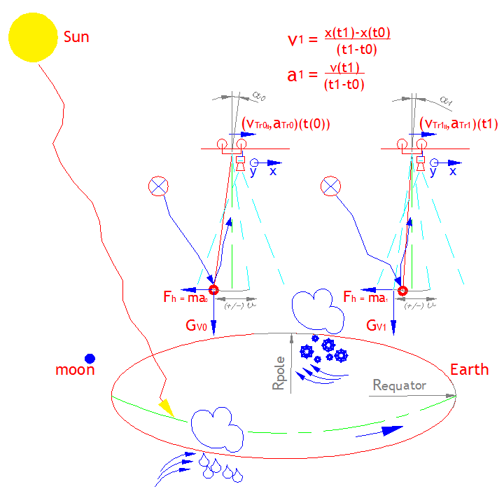
Sway motion measurement under the all forcies of space
The sway motion speed and acceleration measurements
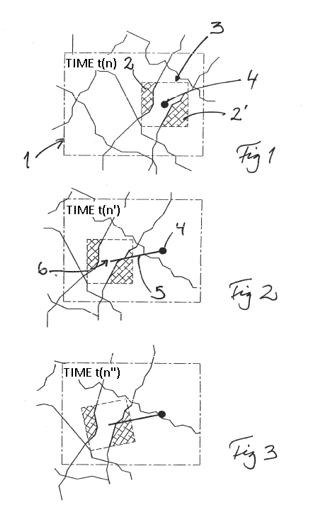
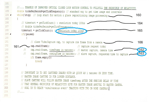
Because image transfer wired or wireless and image data analyzing is slow, our observer has an accurate timer. If this timer has accuracy of e.g. 100ns that would be acceptable. However, any timer resolution which can arrange observer received image in specific order without variation would improve motion speed and acceleration calculations. When image prosessor start or has finished to read its photo sensitive cell, we put that time to image data (in data fusion). All time variations and delays from data transfer, data analyzing, searching ROI results and so on will mostly lose their importance. When we calculate from image the ROI area (Region of interest) movement speed f(focal length, lens magnitude, time) from two images, the motion control internal delay and possible data transfer delays, like wireless connection, enable final control value correction. Furhermore, we loop process now typically within 20-80ms process time, the system itself correct instantly its possible misadjustment.
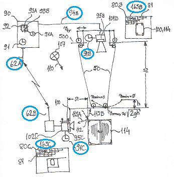
Put down image receice time 163AB and transfer information to controller
With accurate camera prosessor timer data added to image will increase control usability 50=supportsystem(not predictable), 62AB=Radiolink, 80BC=imagedata 91ABC=prosessor timers, 92=CPU, 93AB=cores, 94B=cable or lightcable, 95BC=fotocell, 101B,102B=observer, 107=any light source, 114=body to be followed, 163BC=observer accurate time in nanosecond resolution S1,S2=observer distance 500=moving observer 101B motion machinery vmax=Newtonian sway speed with 'g' is unaccurate
Picture 5:Nanotech motion detection
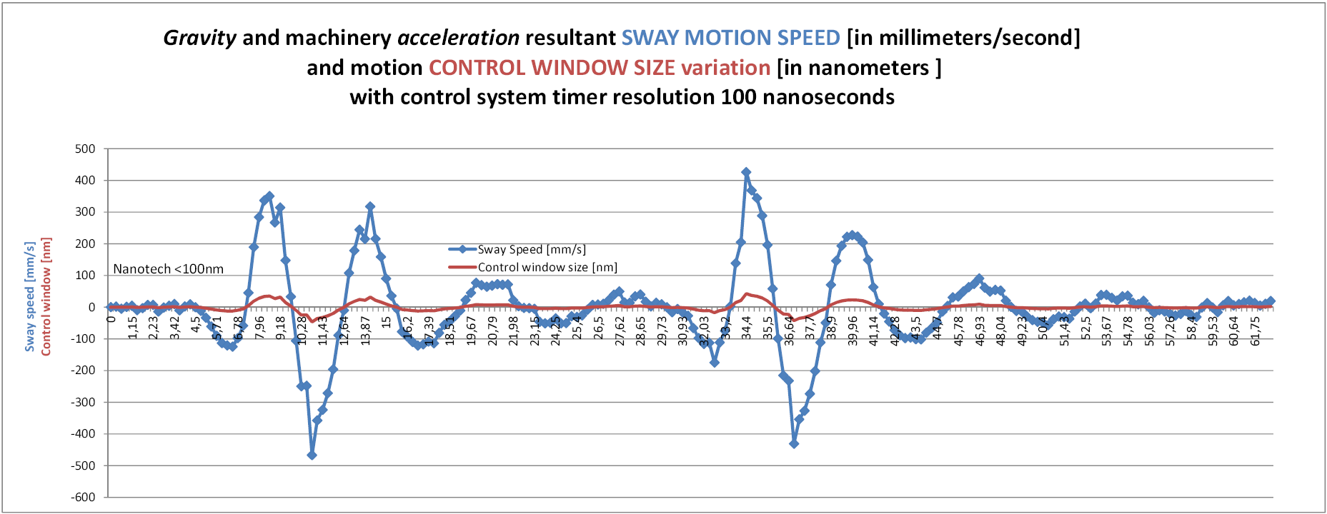
Estimation about sway motion detection accuracy From 'Sway'-page can be found real time sway motion speed control sequency. When our control system clock resolution is 100 ns we get a result, that one second (1s) include 10 000 000 possible tick counts. That is also equal to sample time frequency of 10 MHz. From examble we can see the optical data detect interval time window when observer has similiar timer as standard embedded computer has. If optic motion detection sample capture time stamp accuracy is 100 ns or less, distance measurement accuracy variation shall be less than 100 nm. For WINDOWS applications it is possible to measure time differency with nanosecond accuracy with QueryPerformanceCounter and QueryPerformanceFrequency functions. This means that when ever we calculate motion speed, the optically detected points distancies we need for speed calculation, distancy measure technology shall fullfill NANOTECH technology accuracy requirements. Optic detection will not slow down object ROI area [112] image reflection. The issue is to improve observer (camera) functionality by adding to it an accurate timer or use an intelligent observer where camera and accurate timer already exits. This does not mean that we could or would like to take a sample and process it every 10 MHz tick. We would like to detect object slow or fast motion as accuare as possible remotely. Remotely means that object may locate near or far. We may adjust optic area size and measuring accuracy with optics to fit ROI detection and its motion to our application requirements. Specification as described enables NANOTECH motion detection for accurate speed and acceleration calculation. When observer saves image's accurate receive time, image can be transfered to remote control system different ways [94B, 62AB] and it's possible to synchronize with other observers when observers clocks are syncronized. Image prosessing search algoritm variation do not disturb motion speed culculation as we currently use remote machine vision control system image receive time for speed calculations before use of any search algorithms. But, forexample use of TCP/IP communication and wireless image transfer lack such image delivery stability which our technology fixes. Also we point out, that machine vision search algorithms do not provide such accuracy as optic motion detection can. Of course machine vision accuracy can improved by optic magnification but there usability and accuracy do not always match. So with one observer planar 2-axis position measurement distance accuracy is mostly much less than NANOTECH specifikations. NANOTECH cell size shall be 1 to 100 nanometers. Again, this Picture 5 Nanotec resolution is not about observers motion speed over it's own coordinate but speed between observer [100,101,108] and a body [114] to be transfered. However, this same motion speed calculation accuracy will be accieved at ANTI-SWAY and CONTROL SWAY motion contol applications as well as in near range REPOSITIONING control. We do not take in count inverter control delays and especially inverter control delay variations will exits, but because of control direct cyclic functions, existing control variations will be overcomed by repeating the cyclic control Picture 1 control flow functions 1. to 6. |
The point is that we get motion speed and acceleration detection data from body of interest on the Earth with the fastest possible speed, v(light in air)=99,97%*c without using Newtonian gravitation acceleration fagtor g. More over, we use only special relative theory based sample detection and control technology to solve motion speed and acceleration adjustments in the curved space. This motion detection solution work everywhere on earth as well as in space the same way except that time of speed may vary according intermediate agent. Air on earth has value of 1,0003 and vacuum 1.
There may also other ways to detect motion but sofar we we find several benefits from our standpoint. Please do hasitate to contact to us if you have any questions or doubts. We would acknowledge your opinion.
